
Welding Book
Introduction:
Welding which is the process of joining two metallic components for the desired purpose, can be defined as the process of joining two similar or dissimilar metallic components with the application of heat, with or without the application of pressure and with or without the use of filler metal. Heat may be obtained by chemical reaction, electric arc, electrical resistance, frictional heat, sound and light energy. If no filter metal is used during welding then it is termed as ‘Autogenous Welding Process’.
During ‘Bronze Age’ parts were joined by forge welding to produce tools, weapons and ornaments etc, however, present day welding processes have been developed within a period of about a century.
First application of welding with carbon electrode was developed in 1885 while metal arc welding with bare electrode was patented in 1890. However, these developments were more of experimental value and applicable only for repair welding but proved to be the important base for present day manual metal arc (MMAW) welding and other arc welding processes.
In the mean time resistance butt welding was invented in USA in the year 1886. Other resistance welding processes such as spot and flash welding with manual application of load were developed around 1905.
With the production of cheap oxygen in 1902, oxy – acetylene welding became feasible in Europe in 1903.
When the coated electrodes were developed in 1907, the manual metal arc welding process become viable for production/fabrication of components and assemblies in the industries on large scale.
Subsequently other developments are as follows:
• Thermit Welding (1903)
• Cellulosic Electrodes (1918)
• Arc Stud Welding (1918)
• Seam Welding of Tubes (1922)
• Mechanical Flash Welder for Joining Rails (1924)
• Extruded Coating for MMAW Electrodes (1926)
• Submerged Arc Welding (1935)
• Air Arc Gouging (1939)
• Inert Gas Tungsten Arc (TIG) Welding (1941)
• Iron Powder Electrodes with High Recovery (1944)
• Inert Gas Metal Arc (MIG) Welding (1948)
• Electro Slag Welding (1951)
• Flux Cored Wire with CO 2 Shielding (1954)
• Electron Beam Welding (1954)
• Constricted Arc (Plasma) for Cutting (1955)
• Friction Welding (1956)
• Plasma Arc Welding (1957)
• Electro Gas Welding (1957)
• Short Circuit Transfer for Low Current, Low Voltage Welding with CO 2 Shielding (1957)
• Vacuum Diffusion Welding (1959)
• Explosive Welding (1960)
• Laser Beam Welding (1961)
• High Power CO 2 Laser Beam Welding (1964)
All welded ‘ Liberty ‘ ships failure in 1942, gave a big jolt to application of welding. However, it had drawn attention to fracture problem in welded structures.
Applications:
Although most of the welding processes at the time of their developments could not get their place in the production except for repair welding, however, at the later stage these found proper place in manufacturing/production. Presently welding is widely being used in fabrication of pressure vessels, bridges, building structures, aircraft and space crafts, railway coaches and general applications. It is also being used in shipbuilding, automobile, electrical, electronic and defense industries, laying of pipe lines and railway tracks and nuclear installations etc.
General Applications:
Welding is vastly being used for construction of transport tankers for transporting oil, water, milk and fabrication of welded tubes and pipes, chains, LPG cylinders and other items. Steel furniture, gates, doors and door frames, body and other parts of white goods items such as refrigerators, washing machines, microwave ovens and many other items of general applications are fabricated by welding.
Pressure Vessels:
One of the first major use of welding was in the fabrication of pressure vessels. Welding made considerable increases in the operating temperatures and pressures possible as compared to riveted pressure vessels.
Bridges:
Early use of welding in bridge construction took place in Australia . This was due to problems in transporting complete riveted spans or heavy riveting machines necessary for fabrication on site to remote areas. The first all welded bridge was erected in UK in 1934. Since then all welded bridges are erected very commonly and successfully.
Ship Building :
Ships were produced earlier by riveting. Over ten million rivets were used in ‘Queen Mary’ ship which required skills and massive organization for riveting but welding would have allowed the semiskilled/ unskilled labor and the principle of pre-fabrication. Welding found its place in ship building around 1920 and presently all welded ships are widely used. Similarly submarines are also produced by welding.
Building Structures:
Arc welding is used for construction of steel building leading to considerable savings in steel and money. In addition to building, huge structures such as steel towers etc also require welding for fabrication.
Aircraft and Spacecraft:
Similar to ships, aircrafts were produced by riveting in early days but with the introduction of jet engines welding is widely used for aircraft structure and for joining of skin sheet to body.
Space vehicles which have to encounter frictional heat as well as low temperatures require outer skin and other parts of special materials. These materials are welded with full success achieving safety and reliability.
Railways:
Railways use welding extensively for fabrication of coaches and wagons, wheel tyres laying of new railway tracks by mobile flash butt welding machines and repair of cracked/damaged tracks by thermit welding.
Automobiles:
Production of automobile components like chassis, body and its structure, fuel tanks and joining of door hinges require welding.
Electrical Industry:
Starting from generation to distribution and utilization of electrical energy, welding plays important role. Components of both hydro and steam power generation system, such as penstocks, water control gates, condensers, electrical transmission towers and distribution system equipment are fabricated by welding. Turbine blades and cooling fins are also joined by welding.
Electronic Industry:
Electronic industry uses welding to limited extent such as for joining leads of special transistors but other joining processes such as brazing and soldering are widely being used. Soldering is used for joining electronic components to printed circuit boards. Robotic soldering is very common for joining of parts to printed circuit boards of computers, television, communication equipment and other control equipment etc.
Nuclear Installations:
Spheres for nuclear reactor, pipe line bends joining two pipes carrying heavy water and other components require welding for safe and reliable operations.
Defence Industry:
Defence industry requires welding for joining of many components of war equipment. Tank bodies fabrication, joining of turret mounting to main body of tanks are typical examples of applications of welding.
Micro-Joining:
It employs the processes such as micro-plasma, ultrasonic, laser and electron beam welding, for joining of thin wire to wire, foil to foil and foil to wire, such as producing junctions of thermocouples, strain gauges to wire leads etc.
Apart from above applications welding is also used for joining of pipes, during laying of crude oil and gas pipelines, construction of tankers for their storage and transportation. Offshore structures, dockyards, loading and unloading cranes are also produced by welding.
Classification of Welding Processes:
Welding processes can be classified based on following criteria;
1. Welding with or without filler material.
2. Source of energy of welding.
3. Arc and Non-arc welding.
4. Fusion and Pressure welding.
- Welding can be carried out with or without the application of filler material. Earlier only gas welding was the fusion process in which joining could be achieved with or without filler material. When welding was done without filler material it was called ‘autogenous welding’. However, with the development of TIG, electron beam and other welding processes such classification created confusion as many processes shall be falling in both the categories.
- Various sources of energies are used such as chemical, electrical, light, sound, mechanical energies, but except for chemical energy all other forms of energies are generated from electrical energy for welding. So this criterion does not justify proper classification.
- Arc and Non-arc welding processes classification embraces all the arc welding processes in one class and all other processes in other class. In such classification it is difficult to assign either of the class to processes such as electroslag welding and flash butt welding, as in electroslag welding the process starts with arcing and with the melting of sufficient flux the arc extinguishes while in flash butt welding tiny arcs i.e. sparks are established during the process and then components are pressed against each other. Therefore, such classification is also not perfect.
- Fusion welding and pressure welding is most widely used classification as it covers all processes in both the categories irrespective of heat source and welding with or without filler material. In fusion welding all those processes are included where molten metal solidifies freely while in pressure welding molten metal if any is retained in confined space under pressure (as may be in case of resistance spot welding or arc stud welding) solidifies under pressure or semisolid metal cools under pressure. This type of classification poses no problems so it is considered as the best criterion.
Processes falling under the categories of fusion and pressure welding are shown in Figures 2.1 and 2.2.

Figure 2.1: Classification of Fusion Welding Processes

Brazing and Soldering:
Both brazing and soldering are the metal joining processes in which parent metal does not melt but only filler metal melts filling the joint with capillary action. If the filler metal is having melting temperature more than 450°C but lower than the melting temperature of components then it is termed as process of brazing or hard soldering. However, if the melting temperature of filler metal is lower than 450°C and also lower than the melting point of the material of components then it is know as soldering or soft soldering.
During brazing or soldering flux is also used which performs the following functions:
• Dissolve oxides from the surfaces to be joined.
• Reduce surface tension of molten filler metal i.e. increasing its wetting action or spreadability.
• Protect the surface from oxidation during joining operation.
The strength of brazed joint is higher than soldered joint but lower than welded joint. However, in between welding and brazing there is another process termed as ‘braze welding’.
Braze Welding:
Unlike brazing, in braze welding capillary action plays no role but the filler metal which has liquidus above 450 ° C but below the melting point of parent metal, fills the joint like welding without the melting of edges of parent metal. During the operation, the edges of the parent metal are heated by oxy-acetylene flame or some other suitable heat source to that temperature so that parent metal may not melt but melting temperature of filler metal is reached. When filler rod is brought in contact with heated edges of parent metal, the filler rod starts melting, filling the joint. If edges temperature falls down then again heat source is brought for melting filler rod. The molten filler metal and parent metal edges produce adhesion on cooling resulting into strong braze weld.

The braze welding filler material is normally brass with 60% Cu and remaining Zn with small additions of tin, manganese and silicon. The small additions of elements improve the deoxidizing and fluidity characteristics of filler metal.
Brazing:
The most commonly used filler metal is copper base zinc alloy consisting of normally 50-60% Cu, approximately 40% Zn, 1% Ni, 0.7 % Fe and traces of Si and Mn, which is brass and termed as ‘spelter’. In some cases around 10% Ni may also be added to filler alloys. Copper base alloys may be available in the form of rod, strip and wire. Silver brazing filler metal may consists of 30-55% Ag, 15-35% Cu, 15-28% Zn, 18-24% Cd and sometimes 2-3% Ni or 5% Sn. Silver brazing alloys are available in form of wire, strip, rods and powders.
Borax and boric acid are commonly used fluxes for brazing with copper base filler metals. Many other commercial fluxes may be available in the form of paste or liquid solution leading to ease of application and adherence to the surface in any position.
Various commonly used method of brazing are followings:
• TORCH BRAZING
Torch brazing utilizes the heat of oxy-acetylene flame with neutral or reducing flame. Filler metal may be either preplaced in form of washers, rings, formed strips, powders or may be fed manually in form of rod.
• DIP BRAZING
In dip brazing components with filler metal in proper form is preplaced at the joint and assembly is dipped in bath of molten salt which acts as heat source as well as flux for brazing. Preplaced preform melts and fills the joint. Another variant is to dip assembled parts in metallic bath and metal of bath fills the joint.
• FURNACE BRAZING
Self fixturing assembly with preplaced filler metal is placed inside electrically heated furnace with temperature control for heating and cooling. These furnaces may also be using protective atmosphere with inert gases like argon and helium or vacuum for brazing of reactive metal components.
• INFRA-RED BRAZING
The heat for brazing is obtained from infra-red lamps. Heat rays can be concentrated at desired area or spot with concave reflectors. Such method of brazing requires automation and parts to be joined should be self fixturing. Filler metal is to be preplaced in the joint. The operation can be performed in air or in inert atmosphere or in vacuum.
• INDUCTION BRAZING
The heat is generated by induced current into the workpiece from a water cooled coil which surrounds the workpieces to be brazed. High frequencies employed vary from 5 to 400 kHz. Higher the frequency of current, shallow is the heating effect while lower frequencies of current lead to deeper heating and so it can be employed for thicker sections. Fluxes may or may not be used during brazing.
• RESISTANCE BRAZING
In resistance brazing the heat is generated at the interfaces to be brazed by resistive heating. The components are connected to high current and low voltage power supply through two electrodes under pressure. Only those fluxes are used which are electrically conductive and filler metal is preplaced.
Fig 3.2: Typical Self Fixturing Brazing Assembly

Soldering:
The soldering filler metal is called solder. The most commonly used solder is lead and tin alloy containing tin ranging from 5 to 70% and lead 95 to 30%. Higher the contents of tin, lower the melting point of alloy. Other filler metal are tin-antimony solder (95% tin and 5% antimony), tin-silver solder (tin 96% and silver 4%), lead-silver solder (97% lead, 1.5 tin and 1.5 silver), tin-zinc solder (91 to 30% tin and 9 to 70% zinc), cadmium-silver solder (95% cadmium and 5% silver). These are available in the form of bars, solid and flux cored wires, preforms, sheet, foil, ribbon and paste or cream.
Fluxes used in soldering are ammonium chloride, zinc chloride, rosin and rosin dissolved in alcohol.
Various soldering methods are soldering with soldering irons, dip soldering, torch soldering, oven soldering, resistance soldering, induction soldering, infra-red and ultrasonic soldering.
Soldering iron being used for manual soldering, consists of insulated handle and end is fitted with copper tip which may be heated electrically or in coke or oil/gas fired furnace. Solder is brought to molten state by touching it to the tip of the soldering iron so that molten solder can spread to the joint surface.
Ultrasonic soldering uses ultrasonics i.e. high frequency vibrations which break the oxides on the surface of workpieces and heat shall be generated due to rubbing between surfaces. This heat melts the solder and fills the joint by capillary action.
Flux Residue Treatment:
When brazing or soldering is completed then the flux residues are to be removed because without removal the residues may lead to corrosion of assemblies.
Brazing flux residues can be removed by rinsing with hot water followed by drying. If the residue is sticky then it can be removed by thermal shock i.e. heating and quenching. Sometimes steam jet may be applied followed by wire brushing.
Soldering flux residues of rosin flux can be left on the surface of joint, however, activated rosin flux and other flux residues require proper treatment. If rosin residues removal is required then alcohol, acetone or carbon tetrachloride can be used. Organic flux residues are soluble in hot water so double rising in warm water shall remove it. Residue removal of zinc chloride base fluxes can be achieved by washing first in 2% hydrochloric acid mixed in hot water followed by simple hot water rinsing.
Arc Welding Power Sources:
The main requirement of a power source is to deliver controllable current at a voltage according to the demands of the welding process being used. Each welding process has distinct differences from one another, both in the form of process controls required to accomplish a given operating condition and the consequent demands on the power source. Therefore, arc welding power sources are playing very important role in welding. The conventional welding power sources are:
Power Source Supply
Power Source Supply
(i) Welding Transformer AC
(ii) Welding Rectifier DC
(iii) Welding Generators AC or DC (Depending on generator)
Welding transformers, rectifiers and DC generators are being used in shop while engine coupled AC generators as well as sometimes DC generators are used at site where line supply is not available. Normally rectifiers and transformers are preferred because of low noise, higher efficiency and lower maintenance as compared to generators. Selection of power source is mainly dependent on welding process and consumable. The open circuit voltage normally ranges between 70-90 V in case of welding transformers while in case of rectifiers it is 50-80 V. However, welding voltages are lower as compared to open circuit voltage of the power source.
Based on the static characteristics power sources can be classified in two categories
• Constant current or drooping or falling characteristic power source.
• Constant potential or constant voltage or flat characteristic power source.
Constant voltage power source does not have true constant voltage output. It has a slightly downward or negative slope because of sufficient internal electrical resistance and inductance in the welding circuit to cause a minor droop in the output volt ampere characteristics.
With constant voltage power supply the arc voltage is established by setting the output voltage on the source. The power source shall supply necessary current to melt the electrode at the rate required to maintain the preset voltage or relative arc length. The speed of electrode drive is used to control the average welding current. The use of such power source in conjunction with a constant electrode wire feed results in a self regulating or self adjusting arc length system. Due to some internal or external fluctuation if the change in welding current occurs, it will automatically increase or decrease the electrode melting rate to regain the desired arc length.

Fig 4.1: Constant Potential or Constant Voltage or Flat Characteristic.

Fig 4.2: Drooping or Constant current or Falling Characteristic.
The volt ampere output curves for constant current power source are called ‘drooper’ because of substantial downward or negative slope of the curves. The power source may have open circuit voltage adjustment in addition to output current control. A change in either control will change the slope of the volt ampere curve. With a change in arc voltage, the change in current is small and, therefore, with a consumable electrode welding process, electrode melting rate would remain fairly constant with a change in arc length. These power sources are required for processes using relatively thicker consumable electrodes which may sometimes get stubbed to workpiece or with non consumable tungsten electrode where during touching of electrode for starting of arc may lead to damage of electrode if current is unlimited. Under these conditions the short circuiting current shall be limited leading to safety of power source and the electrode.
Some power sources need high frequency unit to start the arc, which may be requirement of processes like TIG and plasma arc. High frequency unit is introduced in the welding circuit but in between the control circuit and HF unit, filters are required so that high frequency may not flow through control circuit and damage it. High frequency unit is a device which supplies high voltage of the order of few KV along with high frequency of few KHz with low current. This high voltage ionizes the medium between electrode and workpiece/nozzle starting pilot arc which ultimately leads to the start of main arc. Although high voltage may be fatal for the operator but when it is associated with high frequencies then current does not enter body but it causes only skin effect i.e. current passes through the skin of operator causing no damage to the operator.
Duty Cycle:
Duty cycle is the ratio of arcing time to the weld cycle time multiplied by 100. Welding cycle time is either 5 minutes as per European standards or 10 minutes as per American standard and accordingly power sources are designed. It arcing time is continuously 5 minutes then as per European standard it is 100% duty cycle and 50% as per American standard. At 100% duty cycle minimum current is to be drawn i.e. with the reduction of duty cycle current drawn can be of higher level. The welding current which can be drawn at a duty cycle can be evaluated from the following equation;
Duty cycle and associated currents are important as it ensures that power source remains safe and its windings are not getting damaged due to increase in temperature beyond specified limit. The maximum current which can be drawn from a power source depends upon its size of winding wire, type of insulation and cooling system of the power source.
Table 4.1: Welding Processes, Type of Current and Static Characteristic

Manual Metal Arc Welding:
Manual metal arc welding (MMAW) or shielded metal arc welding (SMAW) is the oldest and most widely used process being used for fabrication. The arc is struck between a flux covered stick electrode and the workpieces. The workpieces are made part of an electric circuit, known as welding circuit. It includes welding power source, welding cables, electrode holder, earth clamp and the consumable coated electrode. Figure 5.1 Shows details of welding circuit.
Figure 5.2 shows the fine molten droplets of metal and molten flux coming from the tip of the coated electrode. The flux melts along with the metallic core wire and goes to weld pool where it reacts with molten metal forming slag which floats on the top of molten weld pool and solidifies after solidification of molten metal and can be removed by chipping and brushing.
Welding power sources used may be transformer or rectifier for AC or DC supply. The requirement depends on the type of electrode coating and sometimes on the material to be welded.
The constant-current or drooping type of power source is preferred for manual metal arc welding since it is difficult to hold a constant arc length. The changing arc length causes arc voltage to increase or decrease, which in turn produces a change in welding current. The steeper the slope of the volt-ampere curve within the welding range, the smaller the current change for a given change in arc voltage. This results into stable arc, uniform penetration and better weld seam inspite of fluctuations of arc length.
The welding voltages range from 20 to 30 V depending upon welding current i.e. higher the current, higher the voltage. Welding current depends on the size of the electrode i.e. core diameter. The approximate average welding current for structural steel electrodes is 35.d (where d is electrode diameter in mm) with some variations with the type of coating of electrode. Table 5.1 shows influence of welding parameters on weld characteristics.
Table 5.1: Welding Variables and Their Influence

The output voltage of the power source on ‘no load’ or ‘open circuit’ must be high enough to enable the arc to be started. A value of 80 V is sufficient for most electrodes but certain types may require more or less than this value.
A manual welding power source is never loaded continuously because of operations such as, electrode changing, slag removal etc. Most MMA welding equipment has a duty cycle of around 40% at maximum welding current.
Coated Electrodes are specified based on core wire diameter. Commonly used electrode diameters are 2, 2.5, 3.18, 4, 5 and 6 mm. Length of electrodes may depend on diameter of core wire ranging from 250 to 450 mm i.e. larger the core diameter larger the length. However, special electrodes may be of 8-10 mm diameter. Table 5.2 gives the details of electrode sizes and currents.
Table 5.2: Size and Welding Current for Stick Mild Steel Electrodes

The electrodes are also specified based on ratio of diameter of coated portion of electrode to core wire diameter. If this ratio is lesser than 1.2 then electrodes are thin coated, if ratio ranges between 1.2 to 1.5 then medium coated and if ratio exceeds 1.5 then electrodes are heavy coated or thick coated. This ratio may vary slightly in different codes.
Thin coated electrodes have very good bridgeability at the joint gap but weld bead has coarse ripples and penetration is also poor. Medium coated electrodes lead to reasonably good bridgeability, medium ripples in weld bead and modest penetration. Thick coated electrodes have poor bridgeability, however, bead appearance is excellent with fine ripples and also excellent penetration.
The ingress of oxygen and nitrogen from the atmosphere to the weld pool and arc environment would cause embrittlement and porosity in the weld metal and this must be prevented. The Actual method of arc shielding from atmospheric nitrogen and oxygen attack varies with different type of electrodes which are in two main categories.
- Bulk of covering material converts to a gas by the heat of the arc, only a small amount of slag is produced. Protection depends largely upon a gaseous shield to prevent atmospheric contamination as in case of cellulosic electrode.
- Bulk of covering material converts to a slag, only a small volume of shielding gas produced as in the case of rutile and basic coated electrodes.
Electrode coating performs many functions depending upon coating constituents, during welding to improve weld metal properties. The important functions are as follows:
- Improve the electric conductivity in the arc region to improve the arc ignition and stabilization of the arc.
- Formation of slag, which;
- Influences size of droplet.
- Protects the droplet during transfer and molten weld pool from atmospheric gases.
- Protects solidified hot metal from atmospheric gases.
- Reduces the cooling rate of weld seam.
- Formation of shielding gas to protect molten metal.
- Provide deoxidizers like Si and Mn in form of FeSi and FeMn.
- Alloying with certain elements such as Cr, Ni, Mo to improve weld metal properties.
- Improve deposition rate with addition of iron powder in coating.
Various constituents of electrode coating are cellulose, calcium fluoride, calcium carbonate, titanium dioxide, clay, talc, iron oxide, asbestos, potassium / sodium silicate, iron powder, ferro-maganese, powdered alloys, silica etc. Each constituent performs either one or more than one functions.
Electrode metallic core wire is the same but the coating constituents give the different characteristics to the welds. Based on the coating constituents, structural steel electrodes can be classified in the following classes;
1. Cellulosic Electrodes
Coating consists of high cellulosic content more than 30% and TiO2 up to 20%. These are all position electrodes and produce deep penetration because of extra heat generated during burning of cellulosic materials. However, high spatter losses are associated with these electrodes.
2. Rutile Electrodes
Coating consists of TiO 2 up to 45% and SiO2 around 20%. These electrodes are widely used for general work and are called general purpose electrodes.
3. Acidic Electrodes
Coating consists of iron oxide more than 20%. Sometimes it may be up to 40%, other constituents may be TiO2 10% and CaCO3 10%. Such electrodes produce self detaching slag and smooth weld finish and are used normally in flat position.
4. Basic Electrodes
Coating consist of CaCO3 around 40% and CaF2 15-20%. These electrodes normally require baking at temperature of approximately 250 ° C for 1-2 hrs or as per manufacturer’s instructions. Such electrodes produce high quality weld deposits which has high resistance to cracking. This is because hydrogen is removed from weld metal by the action of fluorine i.e. forming HF acid as CaF2 generates fluorine on dissociation in the heat of arc.
Table 5.3: Coating Constituents and Their Functions

Classification of Electrodes as per Indian Standard:
Structural steel electrodes were classified as per IS 814:1974 and this code was revised and the revised code is IS 814:1991.
The corresponding code is given on each packet of electrode.
IS 815:1974
As per IS 815 electrodes are designated with letters and digits.
P X X X X X X S
Prefix (P) is either E or R which indicates solid extruded (E) or reinforced extruded (R) Electrode.
1 st digit – Indicates type of coating.
2 nd digit – Indicates weld positions in which electrode can be used.
3 rd digit – Indicates welding current conditions.
4 th and 5 th digit – Indicate UTS and YS of all weld metal.
6 th digit – Requirement of minimum % elongation and absorbed energy in charpy V- notch impact test of weld metal.
Suffix (s) – P – Deep penetration electrode
H – Hydrogen controlled electrode
J, K and L – Amount of metal recovery in case of iron powder electrode
Suffix (s) are optional and may or may not be given if not applicable.
IS 814:1991
As per IS 814 electrodes are designated with letters and digits as given below:
E L X X X X S
In this code E indicates extruded solid electrode, L is a letter to designate type of coating, first digit indicates UTS and YS of deposited weld metal, second digit gives percentage elongation and impact values of weld metal deposited, third digit gives welding positions in which electrode can be used and fourth digit gives the current conditions for the use of electrode.
Suffix(s) are optional and indicate special characteristics of electrode such as H1, H2, and H3 indicate hydrogen controlled electrodes with different amount of diffusible hydrogen J, K, L indicate different amount of metal recovery in weld pool in case of iron powder electrodes and X means radiographic weld quality.
Note: For details see the above codes published by Bureau of Indian Standards (BIS), Manak Bhawan, Bahadur Shah Jafar Marg, New Delhi .
Submerged Arc Welding:
Submerged arc welding is an arc welding process in which heat is generated by an arc which is produced between bare consumable electrode wire and the workpiece. The arc and the weld zone are completely covered under a blanket of granular, fusible flux which melts and provides protection to the weld pool from the atmospheric gases.
The molten flux surrounds the arc thus protecting arc from the atmospheric gases. The molten flux flows down continuously and fresh flux melts around the arc. The molten flux reacts with the molten metal forming slag and improves its properties and later floats on the molten/solidifying metal to protect it from atmospheric gas contamination and retards cooling rate. Process of submerged arc welding is illustrated in Figure 7.1.
Extremely high welding currents can be used without the danger of spatter and atmospheric contamination giving deep penetration with high welding speeds. A proper selection of flux-wire combination can produce welds of very high quality. This makes the process very suitable for the welding of high strength steel at welding speeds much higher than conventional manual metal arc welding. It is found that the desired composition of the weld metal can be more economically obtained through adding alloying elements in the flux and using a relatively unalloyed wire as compared with welding with alloyed wire and ordinary flux.
A continuous consumable wire electrode is fed from a coil through contact tube which is connected to one terminal of power source. Wires in the range 1 – 5 mm diameters are usually employed and with wires at the lower end of this range (upto 2.4 mm) constant-potential DC power source can be used allowing arc length control by the self-adjusting effect. For higher diameter electrodes constant current DC source is used.
Submerged arc welding head may be mounted on self-propelled tractors carrying a flux hopper and the coiled electrode. A suction device may also be carried to recover the unused flux for reuse.
Since the end of the electrode and the welding zone are completely covered at all times during the actual welding operation, the weld is made without the sparks, spatter, smoke or flash commonly observed in other arc welding processes.
Power source requirement may be DC or AC. Normally electrode is connected to positive terminal of DC power source. Sometime depending on the nature of flux AC can be used with single electrode wire or with multiple electrodes where one electrode may be connected to DC and other to AC if independent power sources are to be used.
Electrode wires and fluxes are two major consumables. Wires of structural steel are coated with copper to protect it from atmospheric corrosion and increasing its current carrying capacity while stainless steel wires are not coated with copper.
Flux in submerged arc welding performs more or less the similar functions as the electrode coating in the case of MMA welding, except from generation of shielding gas. However, these fluxes perform additional function of pickup or loss of alloying elements through gas metal and slag metal reactions as the molten flux gets sufficient time to react with molten metal and performs above reactions and then forming slag. Some fluxes require baking before use, to remove moisture which might have been absorbed during storage. Such fluxes should be baked as per manufacturer’s recommendations or at 250–300 ° C for 1 – 2 hours duration before use.
Fluxes are fused or agglomerated consisting of MnO, SiO2, CaO, MgO, Al2O3, TiO2, FeO, and CaF2 and sodium/potassium silicate. Particular flux may consist of some of these constituents and other may not be present. Depending upon the flux constituents the base of flux is decided. Also the basicity index of flux is decided on the flux constituents. The ratio of contents of all basic oxides to all acidic oxides in some proportion is called basicity index of a flux. CaO, MgO, BaO, CaF2, Na2O, K2O, MnO are basic constituents while SiO2, TiO2, Al2O3 are considered to be acidic constituents.
When welding with low basicity index fluxes, better current carrying capacity, slag detachability and bead appearance are achieved while mechanical properties and crack resistance of the weld metal are poor. High basicity fluxes produce weld metal with excellent mechanical properties and resistance to cracking, however, bead appearance and current carrying capacity are poor.
Electrode wire size, welding voltage, current and speed are four most important welding variables apart from flux. Welding current is the most influential variable as it controls electrode melting rate, depth of penetration and the amount of base metal fused. However, very high current shall lead to too much penetration resulting into burn through in the metal being joined, excessive reinforcement and increased weld shrinkage and, therefore, large amount of distortion. On the other hand low current shall lead to insufficient penetration, lack of fusion and unstable arc.
Welding voltage has nominal effect on the electrode wire melting rate but high voltage leads to flatter and wider bead, increased flux consumption and resistance to porosity caused by rust or scale and helps bridge gap when fitup is poor. Lower voltage produces resistance to arc blow but high narrow bead with poor slag removal. Welding voltages employed vary from 22 to 35 V.
If the welding speed is increased, power or heat input per unit length of weld is decreased, less welding material is applied per unit length of weld, and consequently less weld reinforcement results and penetration decreases. Travel speed is used primarily to control bead size and penetration. It is interdependent with current.
Excessive high travel speed decreases wetting action, increases tendency for undercut, arc blow, porosity and uneven bead shapes while slower travel speed reduces the tendency to porosity and slag inclusion.
The electrode size principally affects the depth of penetration for fixed current. Small wires are generally used in semiautomatic equipment to provide flexibility to the welding gun. The small wires are also used in multiple electrodes, parallel wire setups.
The larger electrodes are generally used to take advantage of higher currents and consequently higher deposition rates. Where poor fitup is countered a larger electrode is capable of bridging gaps better than smaller ones.
Variations in submerged arc welding may be single electrode wire and multiple electrode wires i.e. multiple arcs.
Multiple arcs are used to increase deposition rates and to direct the arc blow in order to provide an increase in welding speed. Multiple arcs may also reduce the solidification rate and porosity in the weld metal. Multiple arcs may be used either with a single power source or with separate power sources for each electrode.

Fig 7.3: Influence of Electrode Size on Weld Bead.
Submerged arc welding process has high deposition rate with high depth of penetration. This is continuous welding process with no interruptions as electrode wire is supplied through coil on a spool. Welding is carried out without sparks, smoke or spatter. Weld bead is very clean and smooth. Welds produced are of high quality with good mechanical and metallurgical characteristics.
As the arc is not visible, being covered with the layer of slag, so it necessitates accurate guidance of the welding head on the weld groove, failing which an improper fusion will result. Further, process can be used only in flat or HV positions. Plates of lesser thickness (less than 5 mm) can not be welded because of danger of burn through which may occur. Circumferential welds cannot be made in small diameter components because the flux falls away.
Submerged arc welding is mainly being used for different grades of steels. It is widely being used in shipbuilding, offshore, structural and pressure vessel industries. General fabrication such as fabrication of pipes, penstocks, LPG cylinders, bridge girders and other structures are produced by SA welding. Surfacing for reclamation of worn out parts or for deposition of wear or corrosion resistant layers or for hardfacing layers also employ submerged arc process.
Gas Metal Arc Welding
Gas metal arc welding (GMAW) is the process in which arc is struck between bare wire electrode and workpiece. The arc is shielded by a shielding gas and if this is inert gas such as argon or helium then it is termed as metal inert gas (MIG) and if shielding gas is active gas such as CO2 or mixture of inert and active gases then process is termed as metal active gas (MAG) welding. Figure 9.1 illustrates the process of GMA welding.
Direct current flat characteristic power source is the requirement of GMAW process. The electrode wire passing through the contact tube is to be connected to positive terminal of power source so that stable arc is achieved. If the electrode wire is connected to negative terminal then it shall result into unstable spattery arc leading to poor weld bead. Flat characteristic leads to self adjusting or self regulating arc leading to constant arc length due to relatively thinner electrode wires.
GMA welding requires consumables such as filler wire electrode and shielding gas. Solid filler electrode wires are normally employed and are available in sizes 0.8, 1.0, 1.2 and 1.6 mm diameter. Similar to submerged arc welding electrode wires of mild steel and low alloyed steel, are coated with copper to avoid atmospheric corrosion, increase current carrying capacity and for smooth movement through contact tube. The electrode wire feeding system is shown in Figure 9.2.
Pressure adjusting screw is used to apply required pressure on the electrode wire during its feeding to avoid any slip. Depending on the size and material of the wire, different pressures are required for the smooth feeding of wire with minimum deformation of the wire. Further, wire feeding rolls have grooves of different sizes and are to be changed for a particular wire size.
The range of welding current and voltage vary and is dependent on material to be welded, electrode size and mode of metal transfer i.e. mode of molten drop formed at the tip of electrode and its transfer to the weld pool. This process exhibits most of the metal transfer modes depending on welding parameters.
The range of current and voltage for a particular size of electrode wire, shall change if material of electrode wire is changed. With lower currents normally lower voltages are employed while higher voltages are associated with higher currents during welding. Thin sheets and plates in all positions or root runs in medium plates are welded with low currents while medium and heavy plates in flat position are welded with high currents and high voltages. Welding of medium thickness plates in horizontal and vertical positions are welded with medium current and voltage levels.
Table 9.1 gives the total range of currents and voltages for different sizes of structural steel i.e. mild steel electrodes of different sizes.

Table 9.1: Welding Current and Voltage Ranges for Mild Steel Electrodes
Both inert gases like argon and helium and active gases like CO2 and N2 are being used for shielding depending upon the metal to be welded. Mixtures of inert and active gases like CO2 and O2 are also being used in GMA welding process. For mild steel carbon dioxide is normally used which gives high quality, low current out of position welding i.e. also in welding positions other than flat position. Low alloyed and stainless steels require argon plus oxygen mixtures for better fluidity of molten metal and improved arc stability. The percentage of oxygen varies from 1-5% and remaining is argon in argon and oxygen mixtures. However, low alloy steels are also welded with 80% argon and 20% CO2 mixture.
Nickel, monel, inconel, aluminum alloys, magnesium, titanium, aluminum bronze and silicon bronze are welded with pure argon. Nickel and nickel alloys may sometimes be welded with mixture of argon and hydrogen (upto 5%). Copper and aluminum are also welded with 75% helium and 25% argon mixture to encounter their thermal conductivity. Nitrogen may be used for welding of copper and some of its alloys, but nitrogen and argon mixtures are preferred over pure nitrogen for relatively improved arc stability.
The process is extremely versatile over a wide range of thicknesses and all welding positions for both ferrous and nonferrous metals, provided suitable welding parameters and shielding gases are selected. High quality welds are produced without the problem of slag removal. The process can be easily mechanized / automated as continuous welding is possible.
However, process is costly and less portable than manual metal arc welding. Further, arc shall be disturbed and poor quality of weld shall be produced if air draught exists in working area.
GMA welding has high deposition rate and is indispensable for welding of ferrous and specially for nonferrous metals like aluminum and copper based alloys in shipbuilding, chemical plants, automobile and electrical industries. It is also used for building structures.
TIG Welding
Tungsten Inert Gas (TIG) or Gas Tungsten Arc (GTA) welding is the arc welding process in which arc is generated between non consumable tungsten electrode and workpiece. The tungsten electrode and the weld pool are shielded by an inert gas normally argon and helium. Figures 10.1 & 10.2 show the principle of tungsten inert gas welding process.

Fig 10.1: Principle of TIG Welding.

Fig 10.2: Schematic Diagram of TIG Welding System.
The tungsten arc process is being employed widely for the precision joining of critical components which require controlled heat input. The small intense heat source provided by the tungsten arc is ideally suited to the controlled melting of the material. Since the electrode is not consumed during the process, as with the MIG or MMA welding processes, welding without filler material can be done without the need for continual compromise between the heat input from the arc and the melting of the filler metal. As the filler metal, when required, can be added directly to the weld pool from a separate wire feed system or manually, all aspects of the process can be precisely and independently controlled i.e. the degree of melting of the parent metal is determined by the welding current with respect to the welding speed, whilst the degree of weld bead reinforcement is determined by the rate at which the filler wire is added to the weld pool.
In TIG torch the electrode is extended beyond the shielding gas nozzle. The arc is ignited by high voltage, high frequency (HF) pulses, or by touching the electrode to the workpiece and withdrawing to initiate the arc at a preset level of current.
Selection of electrode composition and size is not completely independent and must be considered in relation to the operating mode and the current level. Electrodes for DC welding are pure tungsten or tungsten with 1 or 2% thoria, the thoria being added to improve electron emission which facilitates easy arc ignition. In AC welding, where the electrode must operate at a higher temperature, a pure tungsten or tungsten-zirconia electrode is preferred as the rate of tungsten loss is somewhat lesser than with thoriated electrodes and the zirconia aids retention of the ‘balled’ tip.
Table 10.1 gives chemical composition of tungsten electrodes as per American Welding Society (AWS) classification.

Table 10.1: Chemical Composition of TIG Electrodes.
Tungsten electrodes are commonly available from 0.5 mm to 6.4 mm diameter and 150 – 200 mm length. The current carrying capacity of each size of electrode depends on whether it is connected to negative or positive terminal of DC power source. AC is used only in case of welding of aluminum and magnesium and their alloys. Table 10.2 gives typical current ranges for TIG electrodes when electrode is connected to negative terminal (DCEN) or to positive terminal (DCEP).

Table 10.2: Typical Current Ranges for TIG Electrodes
The power source required to maintain the TIG arc has a drooping or constant current characteristic which provides an essentially constant current output when the arc length is varied over several millimeters. Hence, the natural variations in the arc length which occur in manual welding have little effect on welding current. The capacity to limit the current to the set value is equally crucial when the electrode is short circuited to the workpiece, otherwise excessively high current shall flow, damaging the electrode. Open circuit voltage of power source ranges from 60 to 80 V.
Argon or helium may be used successfully for most applications, with the possible exception of the welding of extremely thin material for which argon is essential. Argon generally provides an arc which operates more smoothly and quietly, is handled more easily and is less penetrating than the arc obtained by the use of helium. For these reasons argon is usually preferred for most applications, except where the higher heat and penetration characteristic of helium is required for welding metals of high heat conductivity in larger thicknesses. Aluminum and copper are metals of high heat conductivity and are examples of the type of material for which helium is advantageous in welding relatively thick sections.
Pure argon can be used for welding of structural steels, low alloyed steels, stainless steels, aluminum, copper, titanium and magnesium. Argon hydrogen mixture is used for welding of some grades of stainless steels and nickel alloys. Pure helium may be used for aluminum and copper. Helium argon mixtures may be used for low alloy steels, aluminum and copper.
TIG welding can be used in all positions. It is normally used for root pass(es) during welding of thick pipes but is widely being used for welding of thin walled pipes and tubes. This process can be easily mechanised i.e. movement of torch and feeding of filler wire, so it can be used for precision welding in nuclear, aircraft, chemical, petroleum, automobile and space craft industries. Aircraft frames and its skin, rocket body and engine casing are few examples where TIG welding is very popular.
Resistance Welding
Resistance welding processes are pressure welding processes in which heavy current is passed for short time through the area of interface of metals to be joined. These processes differ from other welding processes in the respect that no fluxes are used, and filler metal rarely used. All resistance welding operations are automatic and, therefore, all process variables are preset and maintained constant. Heat is generated in localized area which is enough to heat the metal to sufficient temperature, so that the parts can be joined with the application of pressure. Pressure is applied through the electrodes.
The heat generated during resistance welding is given by following expression:
H = I 2 R T
Where, H is heat generated
I is current in amperes
R is resistance of area being welded
T is time for the flow of current.
The process employs currents of the order of few KA, voltages range from 2 to 12 volts and times vary from few ms to few seconds. Force is normally applied before, during and after the flow of current to avoid arcing between the surfaces and to forge the weld metal during post heating. The necessary pressure shall vary from 30 to 60 N mm-2 depending upon material to be welded and other welding conditions. For good quality welds these parameters may be properly selected which shall depend mainly on material of components, their thicknesses, type and size of electrodes.
Apart from proper setting of welding parameters, component should be properly cleaned so that surfaces to be welded are free from rust, dust, oil and grease. For this purpose components may be given pickling treatment i.e. dipping in diluted acid bath and then washing in hot water bath and then in the cold water bath. After that components may be dried through the jet of compressed air. If surfaces are rust free then pickling is not required but surface cleaning can be done through some solvent such as acetone to remove oil and grease.
The current may be obtained from a single phase step down transformer supplying alternating current. However, when high amperage is required then three phase rectifier may be used to obtain DC supply and to balance the load on three phase power lines.
The material of electrode should have higher electrical and thermal conductivities with sufficient strength to sustain high pressure at elevated temperatures. Commonly used electrode materials are pure copper and copper base alloys. Copper base alloys may consist of copper as base and alloying elements such as cadmium or silver or chromium or nickel or beryllium or cobalt or zirconium or tungsten. Pure tungsten or tungsten-silver or tungsten-copper or pure molybdenum may also be used as electrode material. To reduce wear, tear and deformation of electrodes, cooling through water circulation is required.
Figure 11.1 shows the water cooling system of electrodes.

Fig 11.1: Water Cooling of Electrodes (a) Spot Welding (b) Seam Welding.
Commonly used resistance welding processes are spot, seam and projection welding which produce lap joints except in case of production of welded tubes by seam welding where edges are in butting position. In butt and flash welding, components are in butting position and butt joints are produced.
1. Spot Welding
In resistance spot welding, two or more sheets of metal are held between electrodes through which welding current is supplied for a definite time and also force is exerted on work pieces. The principle is illustrated in Figure 11.2.
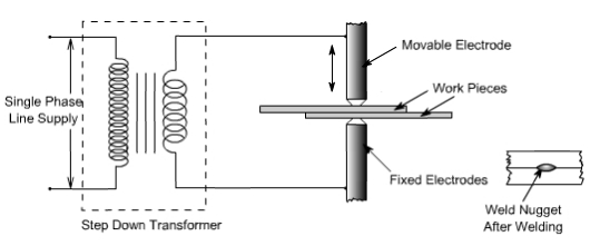
Fig 11.2: Principle of Resistance spot Welding
The welding cycle starts with the upper electrode moving and contacting the work pieces resting on lower electrode which is stationary. The work pieces are held under pressure and only then heavy current is passed between the electrodes for preset time. The area of metals in contact shall be rapidly raised to welding temperature, due to the flow of current through the contacting surfaces of work pieces. The pressure between electrodes, squeezes the hot metal together thus completing the weld. The weld nugget formed is allowed to cool under pressure and then pressure is released. This total cycle is known as resistance spot welding cycle and illustrated in Figure 11.3

Fig 11.3: Resistance Spot Welding Cycle
Spot welding electrodes of different shapes are used. Pointed tip or truncated cones with an angle of 120° – 140° are used for ferrous metal but with continuous use they may wear at the tip. Domed electrodes are capable of withstanding heavier loads and severe heating without damage and are normally useful for welding of nonferrous metals. The radius of dome generally varies from 50-100 mm. A flat tip electrode is used where minimum indentation or invisible welds are desired.

Fig 11.4: Electrode Shapes for Spot Welding
Most of the industrial metal can be welded by spot welding, however, it is applicable only for limited thickness of components. Ease of mechanism, high speed of operation and dissimilar metal combination welding, has made is widely applicable and acceptable process. It is widely being used in electronic, electrical, aircraft, automobile and home appliances industries.
2. Seam Welding:
In seam welding overlapping sheets are gripped between two wheels or roller disc electrodes and current is passed to obtain either the continuous seam i.e. overlapping weld nuggets or intermittent seam i.e. weld nuggets are equally spaced. Welding current may be continuous or in pulses. The process of welding is illustrated in Figure 11.5.

Fig 11.5: Type of Seam Welds

Fig 11.6: Electrode Shapes of Seam Welding
Overlapping of weld nuggets may vary from 10 to 50 %. When it is approaching around 50 % then it is termed as continuous weld. Overlap welds are used for air or water tightness.
It is the method of welding which is completely mechanized and used for making petrol tanks for automobiles, seam welded tubes, drums and other components of domestic applications.
Seam welding is relatively fast method of welding producing quality welds. However, equipment is costly and maintenance is expensive. Further, the process is limited to components of thickness less than 3 mm.
3. Projection Welding:
Projections are little projected raised points which offer resistance during passage of current and thus generating heat at those points. These projections collapse under heated conditions and pressure leading to the welding of two parts on cooling. The operation is performed on a press welding machine and components are put between water cooled copper platens under pressure. Figures 11.7 and 11.8 illustrate the principle of resistance projection welding.

Fig 11.7: Resistance Projection Welding Machine
These projections can be generated by press working or machining on one part or by putting some external member between two parts. Members such as wire, wire ring, washer or nut can be put between two parts to generate natural projection.
Insert electrodes are used on copper platen so that with continuous use only insert electrodes are damaged and copper platen is safe. Relatively cheaper electrode inserts can be easily replaced whenever these are damaged.

Fig 11.8: Formation of Welds from Projections on Components
Projection welding may be carried out with one projection or more than one projections simultaneously.
No consumables are required in projection welding. It is widely being used for fastening attachments like brackets and nuts etc to sheet metal which may be required in electronic, electrical and domestic equipment.
Production of seam welded Tubes:
Welded tubes are produced by resistance seam welding. Tubes are produced from strips which are wrapped on spool with trimmed edges. The width of strip should be slightly bigger than the periphery of the tube to be produced to take care for the loss of metal in flashout. The strip is fed through set of forming rollers to form first the shape of the tube and then it is passed under the seam welding rolls. Under seam welding rolls the edges are butt welded with some flash out on the joint. This flash out is trimmed and then tubes are cut to required size. The process is shown in Figures 11.9 & 11.10.

Fig 11.9: Forming of Tube from Strip

Fig 11.10: Seam Welding of Tube
Welding Defects
The defects in the weld can be defined as irregularities in the weld metal produced due to incorrect welding parameters or wrong welding procedures or wrong combination of filler metal and parent metal.
Weld defect may be in the form of variations from the intended weld bead shape, size and desired quality. Defects may be on the surface or inside the weld metal. Certain defects such as cracks are never tolerated but other defects may be acceptable within permissible limits. Welding defects may result into the failure of components under service condition, leading to serious accidents and causing the loss of property and sometimes also life.
Various welding defects can be classified into groups such as cracks, porosity, solid inclusions, lack of fusion and inadequate penetration, imperfect shape and miscellaneous defects.
1. Cracks
Cracks may be of micro or macro size and may appear in the weld metal or base metal or base metal and weld metal boundary. Different categories of cracks are longitudinal cracks, transverse cracks or radiating/star cracks and cracks in the weld crater. Cracks occur when localized stresses exceed the ultimate tensile strength of material. These stresses are developed due to shrinkage during solidification of weld metal.

Fig 13.1: Various Types of Cracks in Welds
Cracks may be developed due to poor ductility of base metal, high sulpher and carbon contents, high arc travel speeds i.e. fast cooling rates, too concave or convex weld bead and high hydrogen contents in the weld metal.
2. Porosity
Porosity results when the gases are entrapped in the solidifying weld metal. These gases are generated from the flux or coating constituents of the electrode or shielding gases used during welding or from absorbed moisture in the coating. Rust, dust, oil and grease present on the surface of work pieces or on electrodes are also source of gases during welding. Porosity may be easily prevented if work pieces are properly cleaned from rust, dust, oil and grease.Futher, porosity can also be controlled if excessively high welding currents, faster welding speeds and long arc lengths are avoided flux and coated electrodes are properly baked.

Fig 13.2: Different Forms of Porosities
3. Solid Inclusion
Solid inclusions may be in the form of slag or any other nonmetallic material entrapped in the weld metal as these may not able to float on the surface of the solidifying weld metal. During arc welding flux either in the form of granules or coating after melting, reacts with the molten weld metal removing oxides and other impurities in the form of slag and it floats on the surface of weld metal due to its low density. However, if the molten weld metal has high viscosity or too low temperature or cools rapidly then the slag may not be released from the weld pool and may cause inclusion.
Slag inclusion can be prevented if proper groove is selected, all the slag from the previously deposited bead is removed, too high or too low welding currents and long arcs are avoided.

Fig 13.3: Slag Inclusion in Weldments
4. Lack of Fusion and Inadequate or incomplete penetration:
Lack of fusion is the failure to fuse together either the base metal and weld metal or subsequent beads in multipass welding because of failure to raise the temperature of base metal or previously deposited weld layer to melting point during welding. Lack of fusion can be avoided by properly cleaning of surfaces to be welded, selecting proper current, proper welding technique and correct size of electrode.

Fig 13.4: Types of Lack of Fusion
Incomplete penetration means that the weld depth is not upto the desired level or root faces have not reached to melting point in a groove joint. If either low currents or larger arc lengths or large root face or small root gap or too narrow groove angles are used then it results into poor penetration.

5. Imperfect Shape
Imperfect shape means the variation from the desired shape and size of the weld bead.
During undercutting a notch is formed either on one side of the weld bead or both sides in which stresses tend to concentrate and it can result in the early failure of the joint. Main reasons for undercutting are the excessive welding currents, long arc lengths and fast travel speeds.
Underfilling may be due to low currents, fast travel speeds and small size of electrodes. Overlap may occur due to low currents, longer arc lengths and slower welding speeds.


Fig 13.6: Various Imperfect Shapes of Welds
Excessive reinforcement is formed if high currents, low voltages, slow travel speeds and large size electrodes are used. Excessive root penetration and sag occur if excessive high currents and slow travel speeds are used for relatively thinner members.
Distortion is caused because of shrinkage occurring due to large heat input during welding.
6. Miscellaneous Defects
Various miscellaneous defects may be multiple arc strikes i.e. several arc strikes are one behind the other, spatter, grinding and chipping marks, tack weld defects, oxidized surface in the region of weld, unremoved slag and misalignment of weld beads if welded from both sides in butt welds.